Monday, October 27, 2008

Timer with 2 Digit 7 Segment Display

Below is the schematic for a 2 digit 7 segment display using an microcontroller to drive them. This can be used also for large 5 inch LEDs.

This program/hex file for this circuit can can be downloaded here.

Free Image Hosting at www.ImageShack.us

QuickPost Quickpost this image to Myspace, Digg, Facebook, and others!

Sunday, April 13, 2008

Vibration / Sound Activated Switch

Someone asked me for a circuit for vibration or sound activated switched in a forum. I had drawn this quickly by hand.

The sound is detected by the electret microphone then is amplified by the PN2222 NPN transistor. Then the amplified signal is DC converted by the 2 1n4148 diodes.

A comparator is then used to detect the right voltage set by the potentiometer at the inverting input. A small hysteresis is added. The last NPN transistor is the one to drive a relay and with another 1n4148 diode to protect it from the reverse EMF generated by the relay coil when the transistor goes off.

Tuesday, March 11, 2008

3V Input to 5V/TTL Converter

This circuit converts 3V input to be connect to 5V or TTL device. This is a very simple common-base configuration circuit and uses 4 components only. R1 and R3 are used to pull-up voltage to 3V and 5V respectively if no 3V input is present. While R2 is used to limit the base current of Q1 when its start to conduct when the input becomes low.

Monday, March 10, 2008

Telephone Ring Indicator Using LED Lamp

This is the circuit for Telephone Ring Indicator Using LED Lamp. The telephone ring is typically 90VAC RMS so is more than enough to light a single LED. C1 is used for DC blocking thus no OFF-HOOK condition at standby state. R1 is to dissipate excess voltage, while D1 and C2 rectifies it to positive DC voltage. D2 regulates the voltage to 9VDC with R2 again limits the current of the LED during ringing.

Tuesday, March 04, 2008

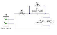
220V Line Powered LED Lamp

To connect a single LED lamp to the 220V AC line, the minimum need are a series a high voltage capacitor and a resistor. A diode also in parallel with the LED in reverse polarity connection.

The diode prevents reverse voltage breakdown of the LED. The resistor is needed to prevent in-rush (surge) current to the capacitor if from OFF (discharged). An additional resistor in parallel to the capacitor to bleed the charged voltage when the circuit is OFF to prevent electric shock.

Computing for values:
I(led) = 0.02
Xc = V/I(led) = (220-3)/.02 = 10850
Cmin = 1/(2*pi*Xc) = 1/(2 *pi * 60 * 10850) = 0.24uF = 0.22uF nearest value

Friday, February 22, 2008

Very Simple 2 Transistor LED Flasher Circuit


This is a very simple 2 transistor circuit. It is very easy to construct. The parts can even be soldered without using a PCB.

This can be a your first circuit to construct for learning and introduction to electronics.

Thursday, December 27, 2007

My New Blog

I have create a new electronics and programming blog. Here I will post electronic projects, circuits and codes. Please visit this site.